Steel Mounting Brackets
Ladder Bars and Hair pin radius rods can be installed straight along the chassis rails or angled towards the centre of the chassis to allow for the differential to ride up over bumps in the road with out binding up the rear suspension arm bushes.
However one of the problems when installing a ladder bar supported rear end is that not all of us can cut out the floor pan like a tubbed drag car. Add to this the array of different chassis and floor pans with a different height step up for diff clearance, from early hot rods to mono construction muscle cars to pick up trucks and 50’s lead sleds and 60’s yank tanks, of which dimensions can lead to some hair pulling and much garage swearing late at night when a mass produced ladder bar kit just does not fit.
The problem is more in trying to get the ladder bar or hair pin radius rod to sit level at ride height and attach to the diff and to the car in a clean and functional way. All chassis shapes are different and the chassis step up dimension at the rear is relative to how far the cabin floor steps down in the middle. Some chassis are relatively flat like a pick up truck or an A’ model chassis and others are really stepped up like an AC Cobra.
The above pics shows a rod under contruction fitted with hair pin radius rods to locate the rear axle and a perpendicular to the chassis pan hard bar.
What brackets you choose will depend on how you are going to brace the chassis to attach the front of the hair pins or ladder bars to the frame. The diameter of the tyre you are going to run will determine the axle centre line height, then you will have to determine the ride height relative to the body that you are going to run.
So please don’t ask us for a standard kit to suit your vehicle …… are you building a custom car or what? 
. We have a range of custom brackets so you can sort it out properly and if you do not see what you want, send us a sketch and we can make it for you.
We have identical paired brackets that allow you to angle the hair pin or ladder bar towards the centre of the chassis for both the chassis mount and the diff mounts. We also have a range of pan hard bar brackets and we can custom make street legal bushed rod end pan hard bars for the street.
The picture below illustrates the subtle differences between body styles

The critical dimensions of each bracket are shown in a picture under each component listed here in the Kustom Bitz shopping cart. Our standard diff brackets have 150mm hole centres for the bars and we have diff tube diameters in 64mm, 71mm, 76mm and 84mm which will cover 90% of all Borg Warner, Falcons, Fairlane, Mustang, Holden, Ford 8 ¾ diffs and the popular Ford 9 inch diffs from tank Fairlane, GT Falcon, to big bearing aftermarket diff housings. The important thing to note is measure your diff, because all models are different. The steps we have chosen for our sizes means that there is not much to linish or file off if your diff tube size is close to one of our standard sizes.

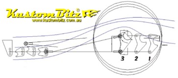
The other important dimension to know is the brackets are set to get either the bottom bar of a typical drag racing ladder bar parallel with the ground OR a typical hair pin radius rod of which should be symmetrical in its installation which typically means the front rod end will be in the centre of height ~ relative to the diff end rod ends. i.e. The front mount position is usually different to a drag racing style ladder bar, because they are different shapes. See diagram on main info sheet above and below.

As we stated above the rear diff bracket holes are 150mm apart and the top hole is used as a reference to the diff axle centre line to identify our three sizes. Shape 1 the top hole is 45mm above the axle centre line, Shape 2 the top hole is 20mm above the axle centre and Shape 3 the top hole is 5mm below the axle centre. This give you a 50mm window to play with which will cover most variations, in any case Size 3 places the bars pretty low relative to the diff and it is about as low as you can go with a 15inch diameter rim. NOTE that in the diagram above and below size 3 is shown on the left then size 2 and then size 1 far right. Note that the bottom bracket hole is in the same height position on the drawing and you can see the obvious different positions of the axle centre line. So size 3 places the wheel further up into the wheel well for deep stepped chassis and size 1 is for not so deep wheel wells. The rest is up to you  .
.

If you are installing the bars inline with the chassis rail then use a pair of “SHORT” brackets per side. However if you wish to angle the bars toward the centre of the chassis to meet street registration requirements then you will need one “SHORT” and one “LONG” bracket per side to provide enough angle for you to play with positioning of the bars.